


Feedrail FH Heavy Duty Trolley Series
Heavy Duty Crane & Hoist Electrification Systems for Movable Trolley Service
General Information:Feedrail® systems are capable of providing multi-purpose trolleys or stationary plug-ins for installations requiring a source of electrical power which can be reconfigured without rewiring. These systems provide moveable outlets for electrical power along their entire length. The systems are especially suited for use where conventional wire systems would be cumbersome and costly. Plug-in Jacks with stationary power take-offs, are available for all Feedrail® systems. The busway-supported outlets called “trolleys” (Feedrail® 60 system only) make contact with the enclosed bus bars and provide a continuous moveable connection for electrical devices. The trolleys are easily inserted and removed through door-busway sections. As additional outlets are needed, trolleys (Feedrail® 60 System only) or stationary plug-ins can be quickly and efficiently inserted, their numbers being limited only by the current-carrying capacity of the busway and the capacity of each outlet. Reliable design assures uniform contact pressure, limiting work stoppages due to electrical and mechanical interruptions in supplying power. Advantages of these systems include low installation costs with complete re-usability; ease of adding outlets as required; electrical and personnel safety; compactness; dependability and minimum maintenance expense. All “busway (track) sections” are factory assembled for ease in handling and rapid installation. No special tools are required. Systems are designed for indoor use in non-hazardous, non-corrosive, dry atmosphere. |
Basic Information:
More Information:
|
UL & CSA Listed
Feedrail® is listed by Underwriter’s Laboratories, Inc. (U.L.) under BUSWAYS AND ASSOCIATED FITTINGS (File E11348 for Feedrail® / File E165922 for Electro-Rail® ) and as a CRANE AND HOIST ELECTRIFICATION SYSTEM (File E31188 for Feedrail® ). Feedrail® is also listed by the Canadian Standards Association (C.S.A.) under WIREWAYS AND BUSWAYS (File LL-7907 for Feedrail® / File LL 103287-1 for Electro-Rail® ).


FH Heavy Duty Crane & Hoist System — What It Is and What It Does
Current Carrying Capacity
- No. FH2100 225 amperes (continuous); 300 amperes (intermittent). Trolleys rated 225 amperes (continuous).
- No. FH3100 375 amperes (continuous); 425 amperes (intermittent). Trolleys rated 375 amperes (continuous).
- No. FH5100 500 amperes (continuous); 575 amperes (intermittent). Trolleys rated 500 amperes (continuous).
Voltage
600 volts A.C. - 250 volts D.C.
Track Supports
Supports are of heavy gauge steel. Two supports are required for each track section to provide support every five feet.
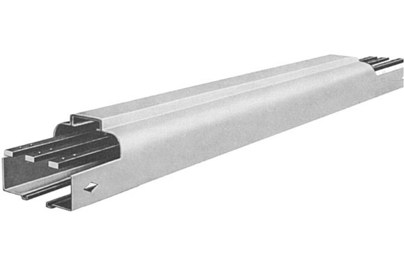
Track
Track sections consist of a brake pressed one-piece 13-gauge zinc coated steel housing and the enclosed current carrying bus bars and insulators, all factory assembeld in convenient lengths ready for easy fool-proof instalation on the job. The lower horizontal portions of the housing serve as smooth, rigid runways for the trolleys.
Heavy Duty track sections are available in various types - Plain, Door, Sectionalizing, and Expansion track sections.
Bus Bars are of hard drawn copper. They are amply proprotioned to carry the specified current or 225 / 375 / 500 amperes per pole continuously, or 300 / 500 / 575 amperes per pole intermittently, without over-heating.
Bus bar connectors assure full current carrying capacity accross the joints without interferring with the free travel of the trolley contacts.
Insulators are made of a high insulating and arc-resistant material.
Trolleys
Basically, all Feedrail® heavy Duty trolleys have a chassis-insulator-contact assembly. The chassis is of heavy gauge steel. The trolley wheels and guide wheels are of the ball-bearing type. A substantially proprotioned insulator block combines the best insulation properties with high arc resistance.
Feedrail® Heavy Duty trolleys are furnished with silver alloy BRUSH CONTACTS for movement up to 500 feet per minute. For rate of travel or conditions other than above please consult technical service group.
A polarizing tab on the chassis, operating in conjunctin with a stop in the door track section, permits insertion of the trolleys only one way. Equipment grounding may be made through the trolleys. Weights in excess of 40 pounds per trolley are not recommended.
Grounding
For the safety of personnel, the track casings of the Feedrail® system may be used as an equipment grounding conductor for grounding equipment through the individual trolleys.
Equipment grounding may be made by using the grounding lug within the box. track housing must be grounded through conduit or other suitable means.
Feedrail® Heavy Duty systems are designed primarily for indoor services in essentially dry locations. Feedrail® systems are electrified tracks in which the current carrying components are enclosed in protective steel housings. Smooth riding internally track-supported trolleys take off current and provide electric power for crane and hoist or other types of electrification systems.
The Feedrail® Heavy Duty systems have been specifically developed to provide safe electrification for crane bridges, monorail-hoist installations, test lines, machine tools and similar applications.
The Feedrail® Heavy Duty Systems are made up of standardized units, factory assembled for fast, complete installation without on-site fabrications.

Typical Installations
ApplicationsHeavy Duty Feedrail® systems find new applications daily wherever convenient movable power sources of 225, 375 or 500 amperes are needed. There is virtually no limit to thier use. A few applications are illustrated here. |
|
|
|
|


Joining Straight Sections with Coupling Plate
|
|
|
|
|
|


Mounting Reversible End Feed Box
|
|
|
|


Mounting Dead End Cap
|
|

Coupling Sections with Center Feed Box
|
|
|
|


Installing Track Hangers
|
|

Installing Sectionalized Track
|
All Sectionalizing Track sections are coupled in the same manner as Plain Track, shown in Joining Straight Sections with Coupling Plate. Note: The standard sections described in Sectionalizing Track have internal insulators of a size which do not prevent the interrupting of the current to the trolley. The current is not only maintained through the trolley but the circuits on both sides are electrically tied together through the trolley contacts as the trolley passes the sectionalizing insulator. Other special sectionalizing track sections which are used in particular applications do break the current to the trolley. In these cases, two electrically connected trolleys must be used. They must be spaced sufficiently apart so that the contacts of one will be on the bus bars while the contacts of the other are passing the insulator. Unless connected in this manner, power will not be maintained to the trolley contacts as they cross the insulators and arcing at the trolley contacts will occur. Sectionalizing track sections must not be used as a circuit interrupting device. |
Building Expansion Track
At least one Expansion Track section should be installed in each 400 ft. of track run to compensate for the cumulative differences in expansion and contraction between the steel casings and copper bus bars. Additional Expansion Track sections may be required if the installation is subjected to a wide range of temperature changes.
Expansion Track sections must be used wherever an installation is made across a building or structural expansion joint.
The standard 10' Expansion Track section is designed to provide 2" of expansion and 2" of contraction above and below the normal 10' length, at 75°F. At the time of installation, the length of the Expansion Track section must be set in accordance with the table below.
When used at points other than a building or structural expansion joint to compensate for unequal expansion or contraction between the steel track housing and copper bus bars, support the Expansion Track section by the coupling plates at each end and by the center support plates from suitable support brackets.
When used across a building expansion joint, center the Expansion Track section across the building expansion joint and support at each end from coupling plates and from the center support plates. Center support must be on the same side of the building expansion joint as the side of the expansion section stenciled "STATIONARY."
Length Settings for Standard 10' Expansion Track |
|||
|
Installation Temperature |
Distance in Feet * |
||
|
100 |
200 |
400 |
|
|
100°F |
9'11-3/16" |
9'11-5/8" |
9'11-1/4" |
|
75°F |
10' |
10' |
10' |
|
50°F |
10'3/16" |
10'3/8" |
10'3/4" |
|
25°F |
10'3/8" |
10'3/4" |
10'1-1/2" |
|
* Distance Represents: |
|||
Mounting of Heavy Duty Trolleys
|
(2) Insert trolley. If trolley hits polarizing stop, remove, reverse 180° and reinsert. Close track doors. (3) Mount drive bracket in a horizontal plane as shown below. Chains must be parallel with and on the center line of the track. When wiring trolleys, a looped flexible wire cable should be used (not rigid or flexible conduit). The flexible cable should be attached to the trolley so no strain is placed on the trolley by the cable. Trolleys should be allowed to travel freely in the track run. |
|
|


Installation Planning
Before a Feedrail® system can be planned or an estimate of the cost prepared, the electrical and mechanical requirements that the system must meet should be known. The following outlines list the basic data needed for all applications and the additional data required for various specific applications.
Basic For All
- Describe in detail the purpose of the Feedrail® Heavy Duty System. Will it be used with existing equipment?
- How many conductors will be required?
- What voltage and current is to be applied to each conductor? Where is the power source located?
- Details about any special requirements or conditions which the installation must meet such as moisture, corrosive fumes, high or low temperatures, etc.
For Electric Cranes
- Sketch giving number, location, length of crane runways and length of bridge. Show location of building expansion joints, if any.
- How many conductors will be required on each bridge run? - How many for power? - for control? How much current must each conductor carry?
- What is the maximum travel speed of the bridge? - of the hoist?
- List of the crane’s motors — main hoist, auxiliary hoist, bridge travel, trolley travel — giving the type (D.C., wound rotor, squirrel cage, etc.) of each motor and its horsepower and full-load ampere rating.
For Electric Hoists
- Plan view sketch of the rail system on which the hoists will travel, giving the length of run of straight sections, radii of any curves and dimensions of any switches. What is the minimum distance from Feedrail® to crane rail in order to clear hoist? Show location of building expansion joints or expansion joints in the structure from which the Feedrail® will be supported.
- How many hoists will be used and what is the horsepower and full load current rating of each? Include horsepower and full load current rating of travel motors of any of the hoists that are motor propelled. What are the maximum travel speeds?
For Production Machines
- Sketch with dimensions to show the location and space available for the Feedrail® system. Indicate range of roof deflection due to snow loads, temperature changes, etc.
- Plan view showing exact sizes and locations of tailgates. Give location of expansion joints, if any, in the upper door guides and in the hangar roof structure. Indicate size and number of doors and pattern of door movements.
- List the number of conductors required and give voltage and amperage requirement of each. Give horsepower and full load current rating of the motors.
For Special Requirements
- Plan view sketch with all dimensions which are necessary to make clear the location and extent of the Feedrail Heavy Duty. Show the location of the power source.
- Full details about equipment which will be operated from the system, including :
- Horsepower and full-load current rating of any electrical motors.
- Fusing arrangements required.
- Number of outlets needed.
Preventive Maintenance
At all times Feedrail® equipment should be so protected and maintained as to be kept clean and dry.
Before the Feedrail® system is placed in operation, it should be thoroughly checked for horizontal and vertical alignment, adequate track support, and free movement of trolley travel throughout the entire track run. All track, bus bar and feed connections should be mechanically tight. The system should be checked for possible grounds or short circuits. Any paint, grease, or other foreign matter accumulated during construction should be removed from the bus bars, insulation and track interior. Blow out all dust and other loose particles from inside the track.
Expansion sections, when used, must be properly adjusted, located and supported in accordance with installation instructions. Check bus bars and casing for accurate alignment.
Feedrail® is both an electrical and a moving mechanical system and therefore should be included as a part of your Preventive Maintenance Program.
Electrical Maintenance requires:
- Keeping the System dry and clean to prevent electrical leakage or “shorts” across the insulation.
- Maintaining electrical continuity by keeping bus bar contact surfaces clean and joints tight.
Mechanical Maintenance requires:
- Preventing excessive wear.
- Replacing parts showing excessive wear.
The following Preventive Maintenance procedure, periodically performed is recommended:
- Remove, thoroughly clean all trolleys and lubricate the wheels. Feedrail® recommends Grade #1 Bearing Grease. This is softer grease than #2 and allows the grease to penetrate the bearings easier. Inspect contacts for excessive wear. Replace worn wheels and contacts.
- Clean bus bars with Feedrail® Track Cleaning Tools.
- Blow out all foreign particles which have accumulated inside the track.
- Check trolleys for free movement within the track.
Check all track supports, track joints, bus bar and feed connections for tightness.
This procedure should be repeated at regular intervals, consistent with the severity of the operations and usage of the system. Plants operating two or three shifts will require more frequent inspection of the Feedrail® equipment. Feedrail® is not normally recommended for installations subject to vibration, frequent electrical overload, corrosive fumes and other abnormal conditions. However, should such conditions exist, more frequent inspection and maintenance will be required.
Before additional electrical loads are added to the system it should be determined that sufficient capacity is available.
FH Series (Feedrail® HD) – Basic Dimensions/Mounting Methods
Basic Dimensions of Feedrail Heavy Duty Systems
The following are the basic dimensions of the Heavy Duty Feedrail® System. These are offered as a guide only.
Mounting Methods
Examples of the methods commonly used for mounting Feedrail® Heavy Duty Systems track runs are shown below. These methods can be used in existing plants as well as in new buildings. In every case the mounting should be designed to insure a rigid installation in both horizontal and vertical alignment. Rod or strap supports should not exceed 2 feet in length without sway bracing.

Build Your Feedrail FH Heavy Duty Trolley Series
All of the components you'll need to build a brand new Feedrail FH Series system have been organized below by category. It is recommended that you start with Track Sections and work your way through each category in the order they're presented. If you have any questions, please contact us and one of our highly trained Feedrail specialists will respond shortly.
 Track Sections |
 Track Accessories & Hangers |
 Trolleys |
 Track & Busway Cleaning Tools |
 Replacement Parts |
Shop for FH Heavy Duty Trolley Series System Components, Parts & Accessories
All components, parts and accessories for the Feedrail FH Heavy Duty Trolley Series System can be found below. Use the product filter menu to narrow your search.


Feedrail FH Series Heavy Duty 10' Straight Track, 3 Pole, 225 Amp
Item Number: FH2100
Heavy duty 10' straight track for FH Series (Feedrail® HD). 3 poles, 225 amps.
Feedrail FH Series Heavy Duty 10' Straight Track, 3 Pole, 375 Amp
Item Number: FH3100
Heavy duty 10' straight track for FH Series (Feedrail® HD). 3 poles, 375 amps.

Feedrail FH Series Heavy Duty 10' Straight Track, 3 Pole, 500 Amp
Item Number: FH5100
Heavy duty 10' straight track for FH Series (Feedrail® HD). 3 poles, 500 amps.

Feedrail FH Series Heavy Duty 10' Straight Track with Door, 3 Pole, 225 Amp
Item Number: FH2101
Heavy duty 10' straight track with trolley door for FH Series (Feedrail® HD). 3 poles, 225 amps.
Feedrail FH Series Heavy Duty 10' Straight Track with Door, 3 Pole, 375 Amp
Item Number: FH3101
Heavy duty 10' straight track with trolley door for FH Series (Feedrail® HD). 3 poles, 375 amps.

Feedrail FH Series Heavy Duty 10' Expansion Track, 3 Pole, 225 Amp
Item Number: FH2155
Heavy duty 10' expansion track for FH Series (Feedrail® HD). 3 poles, 225 amps.
Feedrail FH Series Heavy Duty 10' Expansion Track, 3 Pole, 375 Amp
Item Number: FH3155
Heavy duty 10' expansion track for FH Series (Feedrail® HD). 3 poles, 375 amps.

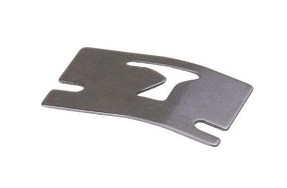
Feedrail FH Series Heavy Duty Coupling Set, 3 Pole, 225 Amp
Item Number: FH2102
Feedrail FH Series heavy duty coupling set. Includes two heavy duty gauge steel plates and cover assembled with screws, which cover track sections and cover the joint. 3 pole, 225 amp.

Feedrail FH Series Heavy Duty Coupling Set, 3 Pole, 375 Amp
Item Number: FH3102
Feedrail FH Series heavy duty coupling set. Includes two heavy duty gauge steel plates and cover assembled with screws, which cover track sections and cover the joint. 3 pole, 375 amp.

Feedrail FH Series Heavy Duty Coupling Set, 3 Pole, 500 Amp
Item Number: FH5102
Feedrail FH Series heavy duty coupling set. Includes two heavy duty gauge steel plates and cover assembled with screws, which cover track sections and cover the joint. 3 pole, 500 amp.

Feedrail FH Series Heavy Duty Center Feed Box, 3 Pole, 225 Amp
Item Number: FH2103
Heavy gauge steel box furnished with positive pressure type solderless connections, for making electrical connections to the power supply between any two adjoining track sections. 3 pole, 225 amp.

Feedrail FH Series Heavy Duty Center Feed Box, 3 Pole, 375 Amp
Item Number: FH3103
Heavy gauge steel box furnished with positive pressure type solderless connections, for making electrical connections to the power supply between any two adjoining track sections. 3 pole, 375 amp.

Feedrail FH Series Heavy Duty Center Feed Box, 3 Pole, 500 Amp
Item Number: FH5103
Heavy gauge steel box furnished with positive pressure type solderless connections, for making electrical connections to the power supply between any two adjoining track sections. 3 pole, 500 amp.

Feedrail FH Series Heavy Duty Reversible End Feed Box, 3 Pole, 225 Amp
Item Number: FH2108
Heavy gauge steel box furnished with positive pressure type solderless connections, for making electrical connectinos to the power supply at the end of a track run. 3 pole, 225 amp.

Feedrail FH Series Heavy Duty Reversible End Feed Box, 3 Pole, 375 Amp
Item Number: FH3108
Heavy gauge steel box furnished with positive pressure type solderless connections, for making electrical connectinos to the power supply at the end of a track run. 3 pole, 375 amp.

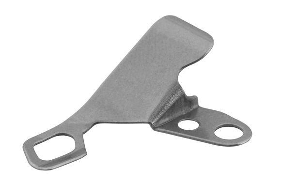
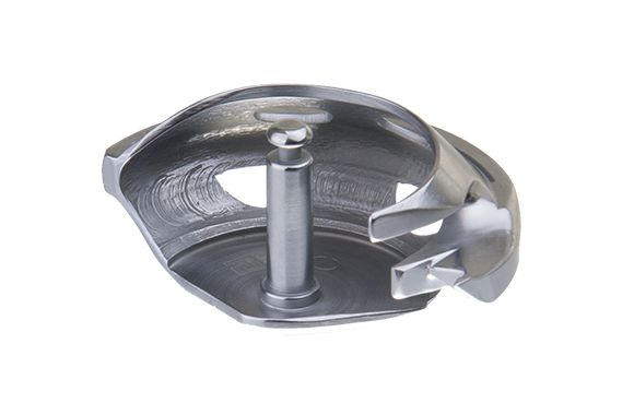
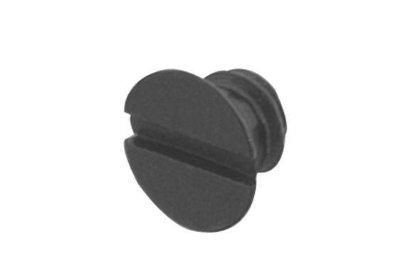
Feedrail FH Series Heavy Duty Dead End Cap
Item Number: FH2107
Feedrail FH Series heavy duty dead end cap.

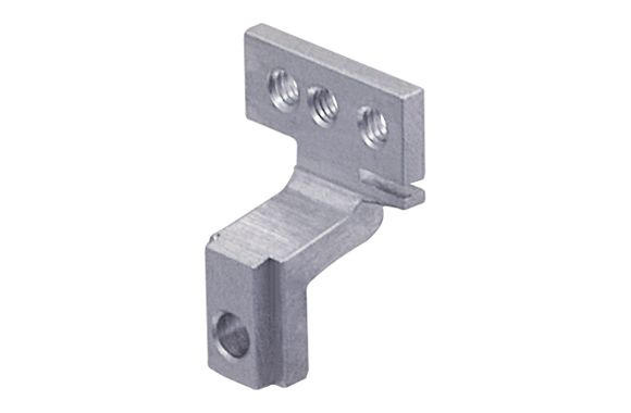
Feedrail FH Series Heavy Duty Track Hanger
Item Number: FH2115
These hangers are made up of pre-formed heavy gauge steel straps for supporting track sections. Two hanger sets are required for each track section to provide support every five feet.

Feedrail FH Series Heavy Duty Trolley for FH2100 Track, 3 Pole, 225 Amp
Item Number: FH2005E
FH Series heavy duty trolley for FH2100 Track, 3 Pole, 225 Amp.

Feedrail FH Series Heavy Duty Trolley for FH22500 Track, 3 Pole, 225 Amp
Item Number: FH22525
FH Series heavy duty trolley for FH22500 Track, 3 Pole, 225 Amp.

Feedrail FH Series Heavy Duty Trolley for FH3100 Track, 3 Pole, 375 Amp
Item Number: FH3005E
FH Series heavy duty trolley for FH3100 Track, 3 Pole, 375 Amp.

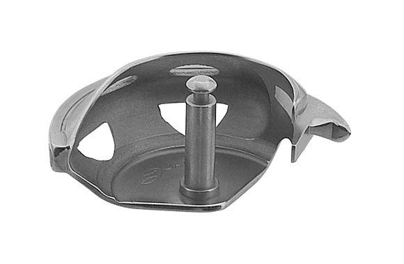
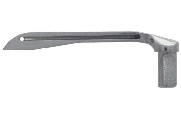
Feedrail FH Series Heavy Duty Dust Remover with Bristle Brushes
Item Number: FH2076
Dust remover with bristle brushes for FH Series (Feedrail(R) HD), 2 or 3 poles.

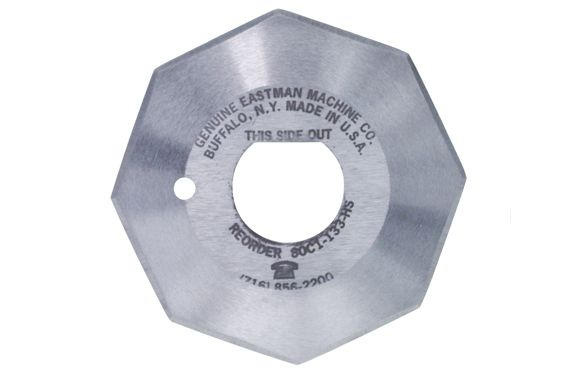
Feedrail FH Series Heavy Duty Bus Bar Cleaner with Stones
Item Number: FH2077
Bus bar cleaners with cleaning stones for FH Series (Feedrail(R) HD), 2 or 3 poles.

Feedrail FH Series Heavy Duty Replacement Door Assembly for HD Track
Item Number: T06661
Feedrail FH Series replacement door assembly for heavy duty track.

Feedrail FH Series Heavy Duty Splice Bar with Screws, 225 Amp
Item Number: S05621P
Feedrail FH Series splice bar assembly with 4 screws, 225 amp.

Feedrail FH Series Heavy Duty Splice Bar with Screws, 375 Amp
Item Number: S05623P
Feedrail FH Series splice bar assembly with 4 screws, 375 amp.

Feedrail Track Connection Bar with Screws, for FR100, FH and FM Series
Item Number: S19321
Feedrail track connection bar with screws, for FR100, FH and FM Series.

Feedrail Connection Bar Fastening Screws for Bottom of Track Casing
Item Number: 301269
Connection bar fastening screws for bottom of track casing for FH Series (Feedrail® 'HD') and FR100 Series (Feedrail® '100').

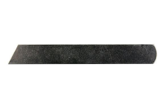
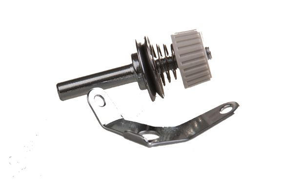
Feedrail FH Series Heavy Duty Cleaning Stone Assembly, 1 Pole
Item Number: S15806
Cleaner stone assembly, 1 pole, for FH Series (Feedrail® 'HD').

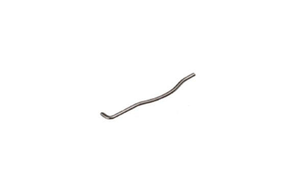
Feedrail FH Series Heavy Duty Cleaning Stone Spring, 1 Pole
Item Number: S04724
Cleaner stone spring, 1 pole, for FH Series (Feedrail® 'HD').

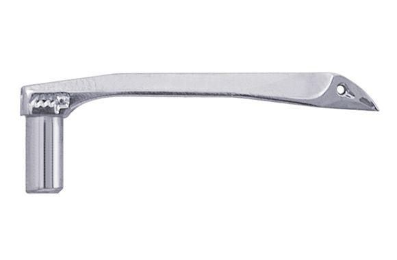
Feedrail Silver Tungston Outside Contact Assembly with Springs for FH Series Heavy Duty, 225 Amp
Item Number: T19389P
FH Series silver tungston contact assembly, outside, with 2 springs, for FH2005E and FH22525 trolleys. 225 amps.

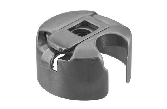
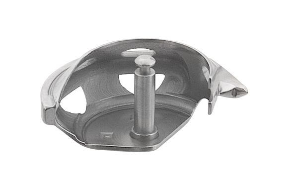
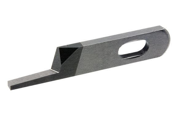
Feedrail FH Series Heavy Duty Trolley Body for FH2005E Trolley, 225 Amp
Item Number: W12016
FH Series trolley body, for FH2005E trolleys. 225 amps.

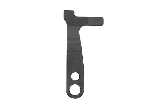
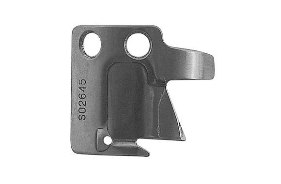
Feedrail FH Series Heavy Duty Trolley Chassis for FH2005E Trolley, 225 Amp
Item Number: W06940
FH Series trolley chassis, for FH2005E trolleys. 225 amps.

Feedrail Silver Tungston Outside Contact Assembly with Springs for FH Series Heavy Duty, 375 Amp
Item Number: S16802
FH Series silver tungston contact assembly, outside, with 2 springs, for FH3005E trolleys. 375 amps.

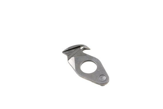
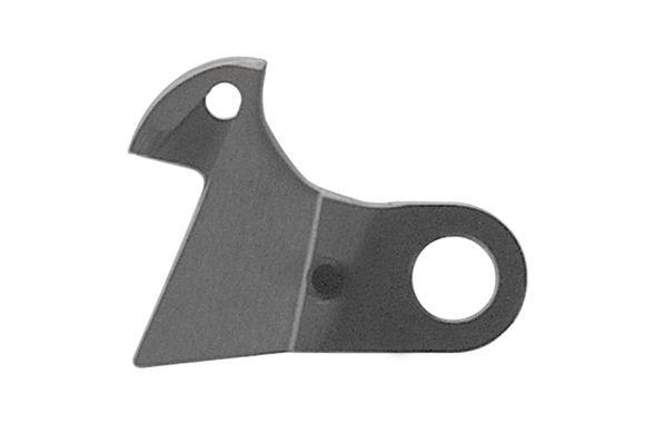
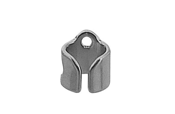
Feedrail FH Series Heavy Duty Contact Retainer for FH3005E Trolley
Item Number: U09790
FH Series contact retainer, for FH3005E trolleys.

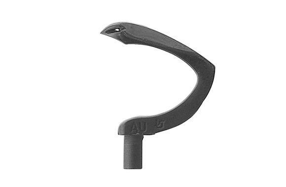
Feedrail FH Series Heavy Duty Trolley Body for FH3005E Trolley, 375 Amp
Item Number: W09759
FH Series trolley body, for FH3005E trolleys. 375 amps.

Feedrail FH Series Heavy Duty Trolley Chassis for FH3005E Trolley, 375 Amp
Item Number: W06607
FH Series trolley chassis, for FH3005E trolleys. 375 amps.